Tuesday, January 27, 2015

How to Install Windows XP in a Virtual Machine

This is a video tutorial explaining how to install the Windows XP operating system in a virtual box on Linux Ubuntu.

VirtualBox is a powerful x86 and AMD64/Intel64 virtualization product for enterprise as well as home use. Not only is VirtualBox an extremely feature rich, high performance product for enterprise customers, it is also the only professional solution that is freely available as Open Source Software under the terms of the GNU General Public License (GPL) version 2. See "About VirtualBox" for an introduction.

Presently, VirtualBox runs on Windows, Linux, Macintosh, and Solaris hosts and supports a large number of guest operating systems including but not limited to Windows (NT 4.0, 2000, XP, Server 2003, Vista, Windows 7, Windows 8), DOS/Windows 3.x, Linux (2.4, 2.6 and 3.x), Solaris and OpenSolaris, OS/2, and OpenBSD.

This is the official web site: VirtualBox

Customizing GRUB

GRUB Documentation

This section documents how I have customized and how I use GRUB version 2 to boot my Notebook PC from several operating systems. The information given here is specific to my own computer but may be useful for other machines too.

Picture: The GRUB Menu on my HP Laptop.

On my Notebook PC, I have three operating systems

  1. Ubuntu 12.10
    Booting from the partition /dev/sda5, an ext4 / (root) partition containing the booting image /boot/initrd.img-3.5.0-17-generic.
    The users are on /dev/sda7, another ext4 partition named /home.
  2. Kubuntu 12.10
    Booting from the partition /dev/sda6, an ext4 / (root) partition containing the booting image /boot/initrd.img-3.5.0-17-generic.
    The users are on /dev/sda7, another ext4 partition named /home.
  3. Windows 7
    Windows boots from the partition /dev/sda1. That is an NTFS type of partition.
To be able to boot anyone of these operating systems, I use GRUB version 2.
I have done some customizations with my GRUB.

Removing memtest from the menu

In the directory /etc/grub.d

If you do not want to have the memtest entries included, simply chmod -x the “20_memtest*” scripts. It will no longer be executable and won't be read into the grub.cfg file the next time you update GRUB.

Changing the GRUB Theme or boot background image of GRUB

To change the boot image when grub2 starts, add a (.png) image of size 1366 X 768 in the directory /boot/grub and regenerate GRUB.

Adding a Boot Tune

You have to modify the file /etc/default/grub. Toward the end, add the tune following the rules explained here:

# Uncomment to get a beep at grub start
#GRUB_INIT_TUNE="480 440 1"
# MLC: Close Encounter of the Third Kind
# MLC: Tempo [[Pitch Duration] ...]
#GRUB_INIT_TUNE="480 900 2 1000 2 800 2 400 2 600 3"
#GRUB_INIT_TUNE="200 900 2 1000 2 800 2 400 2 600 4"
# MLC: Tune tone lowered by 40%.
GRUB_INIT_TUNE="200 540 2 600 2 480 2 240 2 360 4"

CAVEAT
The screen will be be blank the whole time the tune will play.

Creating the grub.cfg File

Once you have made changes to the files, you have to become root and execute the command update-grub:

# update-grub

By the way, if you have installed new operating systems, they will be detected and added to the list of choices in the grub menu.

Making the Last Operating System the Default Choice

With GRUB, you choose an operating system and decide to boot your computer using that operating system. It is very nice if the next time you boot your machine the same operating system is selected by default.

The solution is to edit the file /etc/default/grub and within the file to change the value of the GRUB_DEFAULT variable to “saved”.  It is also very important to define the variable GRUB_SAVEDEFAULT and to set it to "true".
GRUB_DEFAULT=0 specifies the default entry. It counts from 0, like any geeky menu. Changeto anything you like. If you set the entryto GRUB_DEFAULT=saved, it will boot the lastselected option from the previous boot.
Finally, this is en excerpt from my /etc/default/grub file showing the two variables needed to make GRUB remember the last GRUB menu option selected:
Picture: GRUB Remembers the last OS.

Updating and Installing GRUB

After changes have been made to the file /etc/default/grub or if new theme image have been changed in the /boot/grub directory, the GRUB must be regenerated and re-installed.
Acquire the root privileges and execute these two commands:
Regenerate the grub.cfg file.
# update-grub 
Installing GRUB on the MBR (Master Boot Record) of the first SATA hard disk.
# grub-install /dev/sda

More information about GRUB and GRUB 2

Click here for the manual page of GRUB.

From Dedoimedo

GRUB 2 bootloader - Full tutorial

GRUB bootloader - Full tutorial

Mounting NTFS as Read-only

Mounting a Hibernated Windows NTFS File System as Read-Only in Linux

Picture of Tux
Tux
I have a laptop computer with a hard-disk that is partitioned in such a way that it can be booted by three different operating systems.

All the operating systems can share the same data.

The OS are:

  • Windows 7
  • Ubuntu 12.10
  • and, Kubuntu 12.10


So, I have many operating systems installed on the same machine.

I can choose to boot from anyone of them.

Sometimes, I hibernate Windows 7 and I reboot my computer with Ubuntu.

Once in Ubuntu, I want to access files on the Windows 7 partition from Ubuntu. But if Windows was hibernated (instead of shutdown), it is not wise to mount the Windows NTFS file system and then to make changes to it. If you try to mount the Windows NTFS file system using the ntfs-3g command, you will get an error message anyway.  But if you want just to access (i.e. read) files, you can still mount the NTFS file system as "read-only" to get the files without messing up the Windows NTFS volume.

Here is how to do that if the Windows partition you want to access is for example located on /dev/sda2 and you want to mount it into the directory /mnt/sda2 :

Become root:
% su

Execute the following mount command:
# mount -t ntfs-3g -o ro /dev/sda2 /mnt/sda2

After that, the files of your NTFS Windows file system will be accessible (as read-only) on the specified mount point (/mnt/sda2 in this example).

Super Tip About the Mount Command

You can mount a file system (or another directory) into any directory, even in a directory already containing files.
The files of the mounted directory will replace temporarily, and logically, the ones into the mount point.
The original files will reappear when you will unmount (detach) the mounted directory.

Monday, January 26, 2015

Y2K Bug

The Y2K Bug

Really ?

Y2K. The Millennium bug.

Approaching December 31 1999, the whole world was in panic.

Picture: The Y2K Bug.
As a programmer, I knew it was possibly a bit exaggerated, almost a hoax, because except for a few old COBOL programs, probably not into production anymore.

I knew that planes wouldn't crash. I knew that elevator wouldn't get stuck between two levels. 

I was an IT consultant at the CN then, and I was asked to check out a few C programs. I reported that no problem were to be expected in those programs or with the relational databases used, because today memory is not expensive, and the trick of using on two digits to code a year is not used.

Overview

The Y2K Bug, sometimes known as the Millennium Bug or Year 2000 Problem, was a result of digital storage using two-digit abbreviations for years in their systems. In the 1990s, many people were concerned that the rollover between December 31st, 1999 and January 1st, 2000 would result in mass computer failure.

Year 2038 problem

The Year 2038 problem is an issue for computing and data storage situations in which time values are stored or calculated as a signed 32-bit integer, and this number is interpreted as the number of seconds since 00:00:00 UTC on 1 January 1970 ("the epoch"). Such implementations cannot encode times after 03:14:07 UTC on 19 January 2038, a problem analogous to the "Y2K problem" (also known as the "Millennium Bug"), in which 2-digit values representing the number of years since 1900 could not encode the year 2000 or later. Most 32-bit Unix-like systems store and manipulate time in this "Unix time" format, so the year 2038 problem is sometimes referred to as the "Unix Millennium Bug" by association.

The New Profil Language

The New Profil Language

The New Profil language was defined by Mr. Serge Haefelfinger, former president of D.P. Digital Precision Inc.

I have implemented the compiler from the work of two previous programmers. I also wrote the user manual (that you will find at the end of this post).

The compiler accepts as input a New Profil program and outputs a very concise Robofil ISO program.

As a C programmer can write applications for a computer without knowing about the machine language that is specific to the processor on which the applications will run, the NC programmer using the New Profil language does not need to know about the ISO codes language that is used on a particular wire EDM CNC.

Before we had the graphic workstations, the New Profil language was use to write all of our part programs.  The language resembles IBM’s APT but incorporates many new features that are quite useful when the programming of parts is done in a textual environment (using VT100 terminals for example).

Key Features of the New Profil Language

Fast I/O and computations
Conciseness in the ISO output• ISO in implicit or explicit decimal format
Geometric points, lines, and circles can be defined, computed and used in programming
Machine’s movements can be specified with minimal information
Automatic radius (fillets)
Concise syntax
Real type variables
Predefined variaobles
String variables
Mathematical expressions
Automatic tangency indicators
Coordinate selectors
Last entities: P99, L99, C99, …
All Major Words are implemented
Automatic offsets
Program validation (tests of correctness)
Zero length segments support
Elimination of superimposed segments
Change of taper angle
Change of offset
The owner of the plant, a man from Swiss origins named Serge Heafelfinger, he founded D.P. Digital Precision in 1976. Its first equipment was three models Charmilles F45 wire EDM machines. At this time, this machining method was unique and avant-gardist. In fact, D.P. Digital Precision Inc. was the first company in Quebec to introduce wire EDM machining.

He had developed a geometry program using the Basic language on a TRS-80 computer. After that, a programmer named Réal Pepin implemented the routines in Pascal on WICAT Computers. After that, another programmer named Michel Blanchard continued the work because Réal Pepin died suddenly (from a poisoning, I think).

The first project I worked on was to modify the NP3 language so that it could generate ISO codes.

The programmers (NC programmers) had at their disposition two PDP-11 mini-computers.

Picture 1.
Picture 1. A PDP-11 shown with paper DEC LA36 DECwriter II Terminal and a cathode ray tube terminal.
The NC programmers  also used two WICAT System 155 with Vision 2000 terminals (VT-100 compatible with added features such as multiple page switching).

The New Profile Language Reference Manual (in French)


Note: The manual is a Word document and it contains a lot of drawings made in Word. If you preview the document from my Google Drive, the graphics won't display. You need to download the document to your computer in order to see them in the document.

Sunday, January 25, 2015

Wire EDM

What is Wire EDM ?

If you wish to know more about the Wire EDM process, I invite you to watch this seven minutes video clip I have found on YouTube:

Introduction to CNC ISO Programming

Most Wire EDM machines are controlled by ISO 6983 programs.

An ISO program is usually contained in an ASCII text file that can be transferred to the memory of a CNC machine using a serial cable, but it can also be punched on a paper ribbon for older CNC machines.
Picture 1. Examples of punched paper ribbons.

It contains instructions that the numerically controlled machine can execute.

Here are some examples of G functions, M functions, and other words commonly found in ISO programs:
Picture 2. Examples of ISO codes.
The following is a program that cuts a 2" square with the wire offset to the right and a 5˚ taper angle:
Picture 3. An ISO program to cut a 2" square centered at the origin.
Picture 2. An ISO program to cut a 2" square centered at the origin.
Note : 25400 = 25.4 mm = 1" and A5000 is a 5˚ angle.


Porting the New Profil Compiler to UNIX

Porting the New Profil Compiler and the Post-Procssors to UNIX

In July 1991, I was working then for Digital Precision, I have ported the New Profil Compiler and the Post-Processors to UNIX.

The New Profil Compiler was a 12,000 lines program written in Pascal and running on a WICAT computer with the MCS operating system.

To speedup the input and output, the compiler used the low-level operating system calls to perform buffered I/O.

Porting the program to the UNIX operating system was straightforward and easy for me.
All I had to do was to NULL terminate all the strings in the Pascal program and to write in C a module implementing the I/O routines specific to UNIX.

The final executable was finally build from a Pascal source program and linked with a library of I/O routines that I wrote in C to replace the MCS system calls. In other words, I was calling C functions from a Pascal program. This is an excerpt from the compiler main source file illustrating how the interface was declared:

/*****************************************************************************/
/*  Interface with C procedures defined in "wicatio.c".                      */
/*****************************************************************************/
procedure wi_read (var filedesc : text;
                   var buf      : char;
                   nbrec        : integer;
                   var nbread   : integer);                           external;
procedure wi_open (var filename : string;
                   var mode     : string;
                   var filedesc : text;
                   var status   : integer);                           external;
procedure wi_close (var filedesc : text);                             external;

Pictures

The following pictures illustrate what is a WICAT mini-computer and a Silicon Graphics workstation:
Picture 1. A WICAT Computer.
Picture 2. An SGI Personal IRIS Workstation ($50,000.00) in 1991.

PMRC Database Loader

PMRC Database Loader

This post is under construction...

I developed the Performance Monitoring & Rules Compliance (PMRC) Database Loader.

In a nutshell there was information stored in 24 different Lotus Notes databases.

The role of the PMRC database loader was to import these data into a new IBM DB2 database running on an IBM AIX server while of course performing validation on the data to insure the validity of the data.

The documentation was delivered as a website.

PMRC Documentation

In this section, add a video showing the website I have created.

Saturday, January 24, 2015

Integration of IC in MPS

Integration of the IC (Illinois Central) Railroad into MPS (the Motive Power, or locomotive management, System)


In 1999, the CN (Canadian National Railway) merged with the IC (Illinois Central Railroad). For that reason, several computer systems had to be modified to take into account the new information from IC.
Picture 1. CN and IC Merging.

I was an expert with IRIX, X Window, and GL. So, my tasks at that time were to:

  • Install IRIX on the workstations with NFS and the development kit.
  • To modify the graphic system display.

Souvenirs

Prior to MPS, the motive power directors were working in a room. There was a metallic white board representing the country, from Halifax to Vancouver, and little magnets were used to represent and locate the locomotives on that board (cf. picture 2).
Picture 2. Motive Power Directors before MPS.

Eventually, the MPS system was developed. MPS was able to receive messages from the field, because detectors are placed along the rail network and when a locomotive passes near a detector, a message is sent to the mainframe computer so that the system knows in real-time were are located every locomotive on the rail network.

So, MPS was able to display in real-time the locomotive locations on a graphic display.


The MPS directors were then able to send to the field orders about what locomotives to assign to train consists.

This was the MPS control room in Montreal a long time ago, sometimes referred to as the "Star Trek Room" (cf. picture 3):
Picture 3. The MPS Start Trek Control Room.

The Results

This section shows graphically the display before and after the modifications I have done in MPS and I also explains the new functionality of the new display.

Pavement Survey for the Oklahoma Department of Transportation (ODOT)

Pavement Condition Survey in Oklahoma

For the Oklahoma Department of Transportation (ODOT)

GIE Technologies and Dynatest were on a shortlist of possible suppliers to perform the pavement condition surveying of roads in Oklahoma.

I was mandate to perform a survey in Oklahoma.


Here is a summary of the data that was be required for the Oklahoma DOT Control Sites.  Each Control site needed to be run 5 times:

  • Video log images (one pavement view and two right-of-way views) at a 0.005 mi. interval.
  • GPS data at 0.01mi. interval.
  • IRI data at 0.01 mi. interval.
  • Rut data at 10.56 ft. interval.
  • Faulting data; number of faults and standard deviation for each 0.01 mi interval.
  • Geometric data (grade, cross slope and radius of curvature) at a 0.01 mi. interval.
  • Distress data at 0.01 mi. according to ODOT protocols.


Please refer to the ODOT documents that I faxed you for a more detailed description.  The control sites are clearly indicated with paint marks.  If the operator is having trouble to locate them they can call William A Dickinson (405) 555-5555 from the ODOT and he will assist them in locating the sites


Picture Gallery


Friday, January 23, 2015

TLPS - The Transverse Laser Profiling System


This post is under construction...

The ICS was developed to perform...

Technologies:
Windows XP
C++ in Microsoft Visual Studio 8 (2005) IDE
Visual Basic in Microsoft Visual Studio 8 (2005) IDE
.NET Framework 2
Common Language Runtime (CLR)
Multiple Document Interface (MDI) applications
Single Document Interface (SDI) applications
Microsoft Fondation Classes (MFC 8.0)
Modeless Dialog Boxes
Modal Dialog Boxes
Objects Serialization
Afx Threads and critical sections
Software Interrupts
Timer Events (onTimer())
Windows Registry to save and retrieve persistent application’s data
Windows Contextual Help in compressed HTML file
Installation Wizard (Setup.exe)
Point Grey Research Scorpion and Dragonfly high-resolution digital cameras on an IEEE 1394 bus (FireWire™)
PCI-3E US Digital – Three Incremental Encoder with I/O Port, PCI Card
Trimble GPS connected via RS-232 serial port
NMEA (National Marine Electronics Association)
Multiple SATA Hard-drives

Picture Gallery

New feature in development that was not terminated.

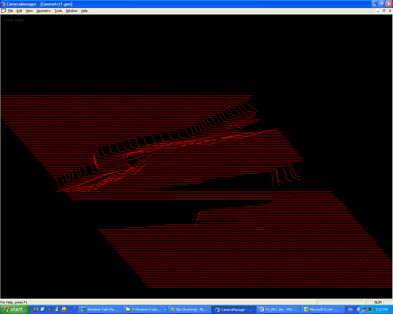
I have started to add a new type of document that the application could open and display: 3D surfaces.

When I stopped working on that project, my application was able to read data for three dimensional lines and to represent them in a view.

For example, consider the following script file:
#
# Filename: \tmp\CapturedGeometry.txt
# Author:   CameraManager
# Date:     Feb/24/2010 08:23:22
#
# Description: This file contains saved geometry.
#

# Line3D is a new CameraManager script instruction that defines a 3-D line
# using a start and an arrival point:
#
# Syntax
#   LINE3D x1 y1 z1 x2 y2 z2;

LINE3D 8.991185 879.958142 0.000000 8.991185 879.958142 0.000000 ;
LINE3D 8.991185 879.958142 0.000000 9.991771 879.932176 0.000000 ;
LINE3D 9.991771 879.932176 0.000000 10.995455 879.723784 0.000000 ;
LINE3D 10.995455 879.723784 0.000000 11.984334 880.386899 0.000000 ;
LINE3D 11.984334 880.386899 0.000000 12.983302 880.456176 0.000000 ;
LINE3D 12.983302 880.456176 0.000000 13.990395 880.047127 0.000000 ;
LINE3D 13.990395 880.047127 0.000000 14.989369 880.116005 0.000000 ;
LINE3D 14.989369 880.116005 0.000000 15.987314 880.245462 0.000000 ;
LINE3D 15.987314 880.245462 0.000000 16.986637 880.293790 0.000000 ;
LINE3D 16.986637 880.293790 0.000000 17.993493 879.898738 0.000000 ;
                                o
                                o
                                o
LINE3D 588.066698 880.431100 2320.000000 589.064360 880.577163 2320.000000 ;
LINE3D 589.064360 880.577163 2320.000000 590.073927 880.022510 2320.000000 ;

The program could parse these instructions to create the following representation using OpenGL:

État sur l’avancement du projet TLPS

Voici un compte-rendu sur l’avancement du projet TLPS.

Ce qui est réalisé et ce qui fonctionne

Le système mesure un profile en retournant une série de points avec des valeurs en X, mesurant la largeur. À chacun de ces points en X, une valeur Z est associée pour déterminer une hauteur ou distance à chacun des ces points en X.
Le système TLPS permet de faire ceci présentement avec des caméras simulées ainsi qu’avec des caméras Dragonfly de Point Grey Research montées dans un détecteur qui associe un laser, une caméra avec double iris et des lentilles polarisantes.
Voici un exemple:

Figure: Profile mesuré par une caméra avec BIRIS.PNG
Image 1. Profile mesuré par une caméra avec BIRIS.
Picture 1. Profile mesuré par une caméra avec BIRIS.

Changer les coordonnées BIRIS(X,Z) en PROFILE(X,Y,Z)

Si on considère les coordonnées en Z (de la hauteur ou distance) comme des coordonnées en Y, alors on peut facilement assimiler un profile à une fonction f(x) = x dans un plan cartésien.
Si on projette cela dans un plan cartésien nous pourrions affirmer que les coordonnées Z sont en fait des coordonnées Y dans un système de coordonnées main droite (right-handed coordinate system  http://en.wikipedia.org/wiki/Cartesian_coordinate_system).
Lorsque le véhicule (camion ou automobile) sur lequel le système TLPS sera installé va avancer, le DMI (Distance Measuring Instrument) va fournir une valeur en Z pour chacun des points (X,Y) mesurés sur la largeur.  Une caméra Dragonfly peut retourner 640 points au maximum sur une largeur à mesurer.  Selon la position de cette caméra, selon qu’elle soit plus près ou plus éloigné de la surface à mesurer, on peut mesurer une bande plus ou moins large.  Donc, dorénavant on aura des points (X,Y,Z), où Z est la mesure alors que le véhicule (DMI) avance.
Le logiciel peut rendre ce profile de niveau, c’est-à-dire le mettre à l’horizontale.  En effet, en effectuant une rotation de la courbe mesurée, le logiciel peut la rendre horizontale.  De plus, il est possible d’effectuer une translation des valeurs en X mesurées par l’instrument.  En d’autres mots, on peut choisir à partir de quelle et jusqu’à quelle valeur en X l’appareil fait une mesure.  Il serait très facile aussi d’ajouter des facteurs d’échelle pour modifier les paramètres de largeur et de hauteur.
Lorsque le système affiches les profiles à l’écran en temps réel, les performances sont intéressantes.  Mais lorsque le système n’affiche rien et qu’il effectue seulement les calculs, alors les performances sont impressionnantes.

Surface en 3-D à Partir de Plusieurs Profiles

Cette section porte sur une recherche que j’ai effectuée pour moi-même et pour me donner de nouvelles idées sur la finalité de ce projet.
Puisque le système TLPS mesure des profiles avec des coordonnées (X,Y,Z), je me suis dit que cela serait une bonne idée que de pouvoir représenter les profiles dans un système 3-D pour générer la représentation d’une surface.
Donc, j’ai écrit quelques lignes de programmation en C++ pour visionner de la géométrie en trois dimensions dans l’application.  C’est un prototype, de la recherche pure seulement.  Je voulais expérimenter et tenter de représenter une surface en 3-D.
En consultant quelques bouquins (cf. les références à la fin de ce document), j’ai développé un prototype.
La surface suivante est constituée 116 profiles avec en moyenne 576 mesures de distances par profile.  Il y a en fait 53 114 lignes constituant cette surface.  Voir la figure 3-D Surface Example 001.PNG.  Les données brutes qui ont servies à générer cette surface sont fournies en attachement dans le fichier CapturedGeometry.zip.
Cette surface a été acquise en filmant le mur du bureau que j’occupais chez GIE.  L’espèce de crevasse à été causée par ma tasse à café que j’ai fait passer dans le faisceau laser.  Les endroits où il n’y a pas de lignes ont été causés par moi quand j’ai passé devant le faisceau laser.
Image 2. Exemple de surface 3D rendue avec OpenGL.

Figure: 3-D Surface Example 001.PNG
Ici, je ne désire pas passer énormément de temps pour expliquer comment j’ai réalisé la représentation de cette surface.  Mon but n’est pas de donner un cours de graphisme en 3-D.  En fait, tout ce que je pourrais dire ici serait une répétition des textes que je donne en référence à la fin de ce document.
Toutefois, je vous montre quelques captures d’écran avec des exemples éloquents.
Dans l’exemple suivant on voit la même surface, mais on voit aussi deux autres documents qui montrent les profiles mesurés pour les images 130 et 158 d’une caméra Dragonfly.  Notez que l’image 158 montre très bien le profile de ma tasse à café:
Image 3. Autre exemple de surface 3D avec details en coupe.


Figure: 3-D Surface Example 002.PNG
L’écran suivant montre trois vues de la même surface.  La seconde vue montre la surface horizontalement (à plat), donc on voit bien sa hauteur.  La troisième vue montre un détail de cette surface:

Image 4. Exemple de surface 3D  avec trois point de vue différents.
Figure: 3-D Surface Example 003.PNG
Pour réaliser cette représentation de surfaces en 3-D, j’ai développé un prototype pour projeter de la géométrie tridimensionnelle sur un écran d’ordinateur.  Le but de ce document n’est pas d’expliquer cela, toutefois, je vous montre un dernier écran qui démontre qu’en effet j’ai réalisé un programme qui permet d’afficher de la géométrie tridimensionnelle sur un écran selon un point de vue quelconque:

Figure: 3-D Viewing System Example 001.PNG
Le but du projet actuel n’est pas de calculer des surfaces pour détecter des crevasses ou des nids-de-poule dans les pavages.  Le but du projet actuel est simplement de calculer l’orniérage d’une route.
Cependant, je crois que les exemples montrés précédemment donnent à penser qu’il serait possible d’effectuer plus de recherche et de développement pour réaliser un système qui serait capable de calculer et d’identifier les crevasses, nids-de-poule, et autres anomalies dans les pavages.  Est-ce que ça vaudrait la peine de faire cela?  Est-ce possible de le faire? Y aurait-il une bonne raison pour le faire?  Je ne le sais pas pour l’instant.
Image 5. Viewing system example.
Image 5.  Viewing system example.

Prochaines Étapes

Actuellement le logiciel peut mesurer des profiles à partir d’une ou plusieurs caméras.

Renommer l’application

Je vais changer le nom de l’application.  Elle va s’appeler TLPS, au lieu de CameraManager.

Renommer BIRIS

Une fois, vous m’avez mentionné qu’il faudrait changer le nom de BIRIS dans l’application.  J’ai fait une classe CBiris (qui est l’adaptation de BIRIS en C vers C++) et à beaucoup d’endroits dans la documentation, dans l’interface avec l’usager (GUI) ainsi que dans le code source, je fais référence à BIRIS.  Je peux facilement effectuer un Global Find and Replace pour changer ce nom par un autre.  Ma question est la suivante: Par quoi devrais-je remplacer le mot BIRIS?  J’attends vos suggestions à ce sujet, Liviu.

Implémenter la logique pour le DMI et le GPS

Je dois implémenter la logique pour faire fonctionner le DMI et le GPS.  J’ai déjà commencé cette tâche d’ailleurs.  Je vais pouvoir rédiger une grande partie de ce code chez-moi en me basant sur ce que j’ai déjà fait dans ICS.  Mais éventuellement, je vais devoir aller chez GIE pour effectuer des tests et les mises au point finales.

Intégrer les profiles mesurés par plusieurs caméras

Maintenant, il faut intégrer les données de mesures de profiles provenant de plusieurs caméras pour former un profile plus large.  Il faut aussi tenir compte de la distance parcourue par le véhicule.  Cette information proviendra du module DMI.  Évidemment, on aura aussi une coordonnée GPS (latitude, longitude et temps) associée à chaque point.
Image 6. Exemple d'assemblage de profiles provenant de N systèmes.

Depuis le début du projet, j’ai toujours eu en tête de créer un système qui pourrait fonctionner de manière distribué.  C’est-à-dire que le système pourrait fonctionner sur plusieurs machines qui communiquent ensemble par des connexions TCP/IP – des network sockets dans un réseau informatique.
Il sera possible de faire fonctionner le système sur une seule machine.  En effet, un seul ordinateur pourrait acquérir des images de caméras Dragonfly, calculer les profiles, acquérir les données du DMI et du GPS,  envoyer les signaux de déclenchement (triggers) aux diverses caméras et faire l’assemblage et la sauvegarde du profile de la route.  Mais, il sera aussi possible de distribuer les traitements sur plusieurs machines pour obtenir une puissance de traitement  théoriquement illimitée.  La configuration distribuée du système sera déterminée par l’utilisateur.  C’est-à-dire que l’utilisateur pourra décider quelle machine fait quoi et quelle machine gère les autres.

Document de type Profile

Je vais créer un nouveau type de document.  Un type de document qui va acquérir la géométrie provenant d’une ou plusieurs caméras qui mesurent et calculent des profiles à l’aide de BIRIS et les intégrer de ce nouveau type de document pour l’afficher dans une nouvelle vue ou bien encore sauver cette nouvelle géométrie.
Ce type de document pourra contrôler des caméras installées sur un seul ordinateur ou encore sur plusieurs machines mises en réseau.

Conclusion

Il reste encore beaucoup de travail à faire.  Je n’ai pas tout détaillé dans ce document.  Je vous tiens au courant des progrès.  N’hésitez pas à communiquer avec moi si vous le désirez.

Marc Lemay
450-661-4602

Références

Fundamentals of Three-Dimensional Computer Graphics
By Alan Watt, University of Sheffield
© 1989 Addison-Wesley Publishers Ltd.
ISBN 0-201-15442-0
Graphics Library Programming Guide
Written by Patricia McLendon
Document Number 007-12-10-040
© 1991, Silicon Graphics Inc.
End of this post.


ICS - The Image Capture System

This post is under construction...

The ICS was developed to perform...

Technologies:
Windows XP
C++ in Microsoft Visual Studio 8 (2005) IDE
Visual Basic in Microsoft Visual Studio 8 (2005) IDE
.NET Framework 2
Common Language Runtime (CLR)
Multiple Document Interface (MDI) applications
Single Document Interface (SDI) applications
Microsoft Fondation Classes (MFC 8.0)
Modeless Dialog Boxes
Modal Dialog Boxes
Objects Serialization
Afx Threads and critical sections
Software Interrupts
Timer Events (onTimer())
Windows Registry to save and retrieve persistent application’s data
Windows Contextual Help in compressed HTML file
Installation Wizard (Setup.exe)
Point Grey Research Scorpion and Dragonfly high-resolution digital cameras on an IEEE 1394 bus (FireWire™)
PCI-3E US Digital – Three Incremental Encoder with I/O Port, PCI Card
Trimble GPS connected via RS-232 serial port
NMEA (National Marine Electronics Association)
Multiple SATA Hard-drives

A simple video


This is a test video

Résumé des tâches accomplies:
Développement de logiciels en C++.

Rédaction de la documentation.

Thursday, January 15, 2015

NFS on IRIX


Configuring NFS
under IRIX 6.5

Prepared by:
Marc Lemay
Wednesday, February 14th, 2001
Last Modified: Thuesday, October 18th, 2001

Conventions used in this document

The percent character ('%') indicates the standard C shell prompt.
The sharp character ('#') indicates the standard C shell prompt for root (commands that must be run by the super-user).

NFS Setup

What Is NFS ?

NFS (Network File System) is a very useful IRIX option.  It enables to share files and directories among several workstations.
NFS is a network service that allows users to access file hierarchies across a network and treat them as if they were local.  File hierarchies can be entire file systems or individual directories.
If NFS is not installed on your workstation, then get it installed.  See Mr. Claudio Testa for this matter.

Configuring NFS

Developers Accessing the XYZ Baseline

The XYZ baseline resides on the hard-disk of the ithree workstation.  If you need to log on ithree (with restrictions), you can use:
Login: secret
Password:
To work with XYZ, a developer needs to have access to the following ithree directories:
/u/development/XYZ
/u/xyzlocal

So, on ithree, the super-user must permit these directories to be mounted by other hosts.  This is achieved by modifying the /etc/exports file.
The ithree /etc/exports file:
#
# NFS exported filesystem database (see exports(4) for more information).
#
# Entries in this file consist of lines containing the following fields
#
# filesystem  [ options ]   [ netgroup ] [ hostname ] ...
#
# Filesystem must be left-justified and may name any directory within a
# local filesystem.  A backslash (\) at the end of a line permits splitting
# long lines into shorter ones.  Netgroup(4) and hostname refer
# to machines or collections of machines to which filesystem is exported.
#
/u/development/v5 indy10 topcweb.cn.ca one topcdev1 topcdev2 topcdev3 topcdev4 topclab3 mtlcfs mtlafs mtlbfs topcstby itwelve nguyen11.cn.ca
/u/local indy10 topcweb.cn.ca one topcdev1 topcdev2 topcdev3 topcdev4 topclab3 mtlcfs mtlafs mtlbfs topcstby itwelve nguyen11.cn.ca
/u/production indy10 topcweb.cn.ca one topcdev1 topcdev2 topcdev3 topcdev4 topclab3 mtlcfs mtlafs mtlbfs topcstby itwelve nguyen11.cn.ca
/u/irel indy10 topcweb.cn.ca one topcdev1 topcdev2 topcdev3 topcdev4 topclab3 mtlcfs mtlafs mtlbfs topcstby itwelve nguyen11.cn.ca
/u/development/XYZ devxyz1 devxyz3 topcdev1 topcdev2 topcdev3 itwelve one xyzlab4
/u/xyzlocal devxyz1 devxyz3 topcdev1 topcdev2 topcdev3 itwelve one xyzlab4

Look at the last two lines (in bold) of that file.  The name of your workstation must appear in the list.  If this is not the case, then edit the file to add the name of your workstation, and execute the command exportfs(1M) on ithree.

# exportfs -a

On your workstation, you must create two mount points (empty directories) to mount the two exported directories from ithree:

% su
Password: XXXXXXXX
# mkdir -p /u/development/XYZ /u/xyzlocal

Now on your own workstation, you must change the file /etc/fstab.  This is the file /etc/fstab actually on topcdev3:
/dev/root /  xfs  rw,raw=/dev/rroot 0 0
ithree:/u/development/v5 /u/development/v5 nfs rw,hard,intr,bg 0 0
ithree:/u/local /u/local nfs rw,hard,intr,bg 0 0
ithree:/u/irel /u/irel nfs rw,hard,intr,bg 0 0
ithree:/u/development/XYZ /u/development/XYZ nfs rw,hard,intr,bg 0 0
ithree:/u/xyzlocal /u/xyzlocal nfs rw,hard,intr,bg 0 0

This file is read when the workstation boots and is used to mount automatically the remote directories.
The last two lines (in bold) indicates that two directories on ithree are to be mounted on this workstation.
If you’ve just edited /etc/fstab, you can mount the remote NFS directories using:

# mount -a -t nfs

(It means mount all directories of type NFS.)

You can check that it worked using the df(1) command:
% df
Filesystem                  Type  blocks     use     avail  %use Mounted on
/dev/root                    xfs 31111632 17433952 13677680  57  /
ithree:/u/irel               nfs 17379152 13224176  4154976  77  /u/irel
ithree:/u/local              nfs 17379152 13224176  4154976  77  /u/local
ithree:/u/development/v5     nfs 17379152 13224176  4154976  77  /u/development/v5
ithree:/u/xyzlocal           nfs 17379152 13224176  4154976  77  /u/xyzlocal
ithree:/u/development/XYZ    nfs 17379152 13224176  4154976  77  /u/development/XYZ

Developers Accessing the XYZ Directory of Other Developers

When a developer adds a new file in the baseline, he is supposed to use the utility xyzadmin (see the document XYZ-LDM Supporting Utilities).  The command xyzadmin will add the new file in the baseline (on ithree) and will create a link to this new file in the personal XYZ directory of every other XYZ developers.  For this reason, the personal XYZ directory of every XYZ developers must be accessible to the other XYZ developers through NFS.

This section explain how to configure that.

Presently, we have six XYZ developers.  Their personal XYZ directories are specified by a variable in a PERL script file in ithree:/u/xyzlocal/bin/xyzfunctions:
%LOCAL = ("marc"     , "/usr/marc/XYZ",
          "zdai"     , "/usr/zdai/XYZ",
          "robert"   , "/usr/robert/XYZ",
          "co"       , "/usr/people/co/XYZ",
          "son"      , "/usr/people/son/XYZ",
          "van"      , "/usr/people/van/XYZ);
By the way, if new programmers are added, or if they change their workstation's name, then this LOCAL variable must be edited of course.
Procedure to configure Marc's workstation:
Create mount points for NFS:
% su
Password: XXXXXX
# mkdir -p /usr/zdai/XYZ
# mkdir -p /usr/robert/XYZ
# mkdir -p /usr/people/co/XYZ
# mkdir -p /usr/people/son/XYZ
# mkdir -p /usr/people/van/XYZ

Edit the file /etc/exports:
#
# NFS exported filesystem database (see exports(4) for more information).
#
# Entries in this file consist of lines containing the following fields:
#
# filesystem  [ options ]   [ netgroup ] [ hostname ] ...
#
# Filesystem must be left-justified and may name any directory within a
# local filesystem.  A backslash (\) at the end of a line permits splitting
# long lines into shorter ones.  Netgroup(4) and hostname refer
# to machines or collections of machines to which filesystem is exported.
#
/ -rw, access=devxyz1:xyzlab4:topcdev1:topcdev2:topcdev3,root=devxyz1:xyzlab4:topcdev1:topcdev2:topcdev3,nohide
Run the command exportfs as root:
# exportfs -a
Edit the file /etc/fstab:
# /etc/fstab for devxyz3.cn.ca
# By Marc Lemay
/dev/root / xfs rw,raw=/dev/rroot 0 0
devxyz1:/usr/zdai/XYZ /usr/zdai/XYZ nfs rw,bg,soft,timeo=10 0 0
xyzlab4:/usr/robert/XYZ /usr/robert/XYZ nfs rw,bg,soft,timeo=10 0 0
topcdev1:/usr/people/co/XYZ /usr/people/co/XYZ nfs rw,bg,soft,timeo=10 0 0
topcdev2:/usr/people/son/XYZ /usr/people/son/XYZ nfs rw,bg,soft,timeo=10 0 0
topcdev3:/usr/people/van/XYZ /usr/people/van/XYZ nfs rw,bg,soft,timeo=10 0 0
ithree:/u/development/XYZ /u/development/XYZ nfs rw,bg,retry=1,timeo=50,retrans=4,soft,0 0
ithree:/u/xyzlocal /u/xyzlocal nfs rw,bg,retry=1,timeo=50,retrans=4,soft,0 0

Execute the mount command as root now:
# mount -a -t nfs
Repeat the same procedure to configure all other workstations.